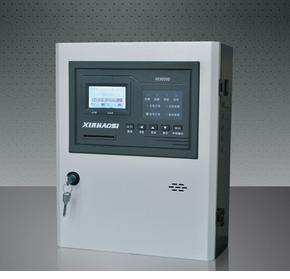
Electrical fire monitoring system application
In the past 10 years, the number of electrical fires in China has topped the total number of fire accidents. According to fire statistics of the Fire Bureau of the Ministry of Public Security, a total of 159,000 fires occurred in 2007 (not including forests, grasslands, military, underground mine fires, the same below). From the direct cause of the fire, electrical fires are the most common. Since then, it has accounted for 28.8% of the total. In 2008, there were 133,000 fires. Electrical causes such as electrical short circuits, overloads, and electrical equipment breakdowns caused 40,000 fires, accounting for 30.1% of the total. The proportion increased by 1.3 percentage points from 2007. The proportion of electrical fire accidents has increased year by year, which is worrying. For the severe electrical fire situation, early forecasting, early warning, and forecasting are the top priorities for firefighting, and eliminating the occurrence of electrical fires at the source has become the focus of attention. The task of preventing and effectively curbing electrical fires is imminent. Relevant state departments have successively formulated or revised relevant standards and specifications and required the installation of electrical fire monitoring and alarm systems in buildings. Independent Led Driver ,Led Built-In Power Supply,Independent Led Power Supply,Independent Constand Power Supply Effort Semiconductor Lighting Ltd. , https://www.effortem.com
Based on the new standard of electrical fire monitoring system (GB14827-2005) and the example of leakage current fire monitoring system of Canon Hi-tech Zone in Zhuhai, this paper introduces the application of Acrel-6000 electrical fire monitoring system in workshops and large public places.
1. Project Profile The Zhuhai Hi-tech Zone New Construction Project site is located in Jinding Industrial Park of Zhuhai High-tech Zone, covering an area of ​​183,934 square meters. This project is mainly for G1 plant, G2 plant, G3 plant, management ridge and power dong 5 Each power circuit in the power distribution area is forecasted and monitored due to electrical leakage and leakage due to electrical leakage, accurately monitors faults and abnormal conditions of electrical lines, and discovers potential fire hazards of electrical fires. The timely alarm reminds personnel to eliminate these hidden dangers. Help companies save labor costs, improve work efficiency, and reduce the probability of fire.
The system detects the leakage current, over-current, and over-temperature signals of each power circuit in the scene, and uses sound and light alarms to accurately alert the staff of the location of line faults and monitor the changes in the fault points. Storage of various fault and operation test signals, display system power status to effectively prevent common electrical fire accidents caused by electrical leakage, and ensure the safety of people's lives and property.
2. Reference Standard This system complies with the People's Republic of China National Standard GB14287.1-2005 "Electrical Fire Monitoring System Part 1: Electrical Fire Monitoring Equipment".
3. Basic composition and working principle of the system 3.1 Basic components According to national standards GB14287-2005 "Electrical fire monitoring system" and related specifications "Design method of electrical fire monitoring system" (provisional regulations), the basic composition of the electrical fire monitoring system should be Including: electrical fire monitoring equipment, residual current electrical fire monitoring detectors, and temperature-based electrical fire monitoring detectors and other three basic product categories. Among them, the residual current type electric fire monitoring detector consists of a monitoring detector and a residual current transformer. The temperature-type electric fire monitoring detector consists of a monitoring detector and a temperature sensor.
The residual current type electric fire monitoring system adopts a hierarchical distributed structure and is composed of a station control layer, a network communication layer, and a field device layer. The system topology is shown in the following figure: Each electrical fire monitoring probe is connected to the communication server through a shielded twisted pair RS485 interface, using a MODBUS communication protocol bus type connection, and then enters the monitoring host through the Category 5 TCP/TP protocol.
1) The field device layer is mainly used for various types of meters and protection devices used for leakage current and temperature signal acquisition and measurement in the connection network, and it is also a necessary basic component element for constructing the monitoring system. It not only shoulders the heavy responsibility of collecting data, but also is a terminal component that executes background control commands. 2) The communication control layer is mainly composed of a communication server, an interface conversion device, and a bus network. This layer is a bridge for data information exchange. Different interface conversion devices provide various interfaces such as RS232, RS422, RS485, SPABUS, and Ethernet, flexible networking methods, support for point-to-point communication, fieldbus networks, Ethernet, and other types. The configuration network. The communication server is mainly used to directly transmit various control commands of the host computer to the field instrument and instrument, and is responsible for collecting, classifying, and storing the data information sent back by the field instrument. The interface conversion device is due to the field instrument or other series. There is a difference in the communication interface between the device and the host computer. It is necessary to perform the conversion before data exchange.
3) Management The monitoring and control layer is for managers who monitor the network. This layer directly faces the user. This layer is also the uppermost part of the system, mainly by the electrical fire monitoring system software and necessary hardware equipment such as computers, human-machine interfaces, printers, UPS and so on. The software part has a good human-computer interaction interface. It reads the various data information collected by the front-end machine through the data transmission protocol and automatically calculates and processes the data. It reflects the operating status of the site by means of graphics, digital display, and sound. Accept the operation command of the management personnel, send and check the execution status of the operation in real time to ensure the normal operation of the power supply unit.