Cyclone milling of large internal threads (figure)
1 Introduction Calculation of thread related parameters Next page 36 Inch Ceiling Fan,36 Inch Outdoor Ceiling Fan,36 Inch Indoor Ceiling Fan,Ceiling Fans 36 Inch With Light Jiangmen MagicPower Electrical Appliances Co.,Ltd. , https://www.magicpowerfans.com
Conventional threading mainly uses thread turning tools to turn threads or use taps, die tapping and buckles. With the development of CNC machining technology, especially the emergence of three-axis CNC machining technology, the more advanced thread machining method - CNC milling of the thread can be realized. Thread milling mainly uses CNC collision and milling machines or machining centers. For small diameter internal thread (≤20mm) commonly used tapping, buckle and other methods to process; for the processing of large precision non-standard internal thread with high hardness and large number of holes, it is more difficult to use these traditional processing methods. Ingersoll's NC-120 internal thread cyclone milling method solves the problem of machining large precision internal threads that are difficult to machine by conventional methods. It can strictly control the medium diameter tolerance, reduce or eliminate the interference of the tooth during the cutting of the tool, greatly improve the precision of the thread to be machined, and the processing efficiency is high. This article mainly introduces the processing methods and programming of cyclone milling.
2 Processing principle and processing method
Processing principle and trajectory
Machining large internal threads on CNC boring and milling machines can be used for cyclone milling. The machining principle is: high-speed rotating forming cutters, whose tool tip rotation circle is always in contact with the outer diameter of the internal thread, and at the same time, the tool The spiral motion is performed around the axis of the workpiece hole. At this time, the metal that interferes with the blade tip is cut by the 60° forming blade, and the thread groove is cut out on the wall of the workpiece hole. The spiral motion is realized by the helical interpolation function of the CNC machine tool. In order to prevent the machining from reaching the bottom of the hole, the interference between the chip and the tool is blocked and the machining part is covered by the chip. The cyclone milling adopts the direction of the cutting from the bottom of the hole. 
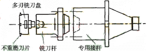
Figure 1 Milling internal thread cutter
Tools and attachments
In the cyclone milling of the internal thread, the blade, the cutter head and the cutter bar on the NC-120 device are borrowed, and the mechanism is shown in Fig. 1. A special post was designed and manufactured with the NC-120 tool holder and cutter head attached to the front and the rear taper handle connected to the machine tool spindle (Fig. 1). The insert is an indexable, non-reground carbide insert with high dimensional and angular accuracy. It can be mounted on a milling cutter disc and has 4 to 6 inserts to form a multi-blade milling cutter disc. The centering rod and the thread at the end of the cutter head are coupled to the cutter rod, and the short taper, the key and the screw at the tail of the cutter rod are fastened to the special cutter rod which can be inserted into the taper hole. The knife has many advantages such as high number of inserts, high precision and good wear resistance. Since the tool is directly connected to the spindle, when selecting the cutter head, the size of the machining pitch and the depth of the screw hole are mainly considered. The screw hole diameter is not the main factor to be considered. The tools for milling threads can also be designed by themselves, but their manufacturing precision must meet the requirements of the work. In order to ensure the dimensional accuracy and surface roughness of the profile, a multi-blade structure is used as much as possible. 
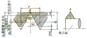
Figure 2 Internal thread profile and tip
The tooth size and the tool point of the internal thread are shown in Figure 2. The thread standard specifies that the tooth profile is to cut the isosceles triangle peak to the H/8 height and use this as the thread nominal diameter. Figure 2 shows the requirements for the threaded clearance. In numerical control milling, in order to make the tip A shown in Fig. 2 coincide with the point B in the tooth size, the maximum diameter D1 of the screw hole must be calculated. Its calculation is as follows:
D1=d+2×H/8=d+H/4
Where H=0.866P, P is the pitch, and the medium diameter tolerance is considered to be 1/3 of the tolerance value, then the D1 diameter will also increase:
D1=d+H/4+e/3
Where e is the medium diameter tolerance value.