Process measures for high-precision gear CNC hobbing (2)
2 hobbing fixture Previous page next page Copper nuts made of all kinds of embossed wire (usually lead brass, such as H59, 3604, 3602). Our daily contact with the embedded knurled copper nuts are processed by precision automatic lathes. The reference standard of embedded knurled copper nut comes from GB/T809, but the technical parameters of all kinds of embedded nuts produced by our company exceed the relevant indexes required by the national standard. Brass Nut,insert nut,knurled nut,injection nut,hex nut Shenzhen Lanejoy Technology Co.,LTD , https://www.szbrassnuts.com
The hobbing fixture must have sufficient strength and can meet the accuracy of gear hobbing. The fixture positioning base is machined on other machine tools and then mounted on the hobbing machine table. It is often not easy to guarantee parallelism.
Therefore, a method of turning the positioning plane on the hobbing machine can be employed. As shown in Figure 1, the hob and the arbor are removed, and a special turret is fixed to the turret by using bolt holes on the turret. A radial cutting procedure is programmed to allow the hobbing machine table to drive the fixture to rotate, and the hobbing frame is fed into the turning tool for radial feeding. Note that the speed of the table should not exceed its rated speed, and the cutting depth of the turning tool is only 0.2mm.
After the fixture is installed on the machine table, as shown in Figure 2, the runout of the three points A, B and C must be checked. The distance between A and B depends on the length of the gear blank (several gears are processed in series when several gear blanks are processed in series) Depending on the sum of the blank lengths, it is generally required to allow the maximum runout amount A to be 0.006 mm and the B and C to be 0.003 mm.
3 Hob system installation and adjustment
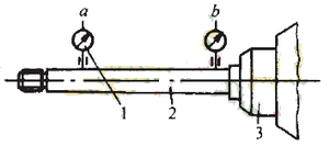
Installation and inspection of the hob bar The shank should be smoothly inserted into the taper hole of the hob spindle and tightened with a tie rod, and then the tie rod should be loosened to eliminate the tensile stress, but the shank should not be disengaged again. Retighten the lever just enough to hold the roller bar and secure it. This is due to the tension generated by the tensioning of the arbor into the spindle taper, causing the struts to be stretched. During the operation of the machine tool, the spindle taper hole expands due to the temperature rise of the machine tool, and the rod is pulled deeper into the taper hole by the tension rod. When the machine is cooled down, the spindle taper hole shrinks, which makes it difficult to remove the tool holder. 
1. Dial indicator 2. Roller bar 3. Spindle
image 3 
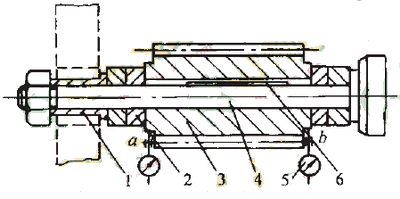
1. Bushing 2. Adjusting washer 3. Hob 4. Hob bar 5. Dial indicator 6. Coupling button
Figure 4
Knurling copper nut is mainly used for hardware Spring, shaped spring, craft gift spring, battery spring, spring antenna,key ring, phosphorus copper spring CNC automatic lathe turning parts (copper car parts, iron, aluminum car parts), metal stamping parts, electronic parts, iron shaft, single Rachel,Rachel, iron pin, non-standard Screw nut,fittings,fasteners, wire forming (wire card holder, Model aircraft landing gear, S hook, R latch, triangle buckle, D buckle) and other hardware products, belonging to the copper nut series.