Application of tool radius compensation in milling machining center
1 Introduction
1) Basic concept of tool radius compensation
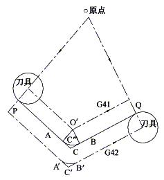
Figure 1 Tool radius compensation in machining
During the contour machining process, since the tool always has a certain radius (such as the radius of the milling cutter or the radius of the molybdenum wire of the wire cutter), the movement path of the tool center does not coincide with the actual contour of the required machined part. As shown in Figure 1, the thick solid line is the contour of the part to be machined, and the dotted line is the tool center path. It can be seen from the figure that during the inner contour machining, the tool center deviates from the inner contour surface of the part by a tool radius value. When machining the outer contour, the tool center deviates from the outer contour surface of the part by a tool radius value. This offset is called tool radius compensation.
2) The role and significance of using tool radius compensation
CNC machine tools generally have the function of tool radius compensation. In the machining, using the tool radius compensation function of the numerical control system, it is possible to avoid the cumbersome calculation in the numerical control programming process, and only need to calculate the coordinate value of the starting point of the tool center trajectory. At the same time, with the tool radius compensation function, it is also possible to realize the functions of roughing and finishing of the same program and processing of the same program.
3) How to use the tool radius compensation command
According to the ISO standard, when the tool center path is on the left side of the forward direction of the programming track, it is called left tool compensation, which is represented by G41; when the tool center track is on the right side of the programming track forward direction, it is called right tool compensation, which is indicated by G42; When the tool radius compensation is canceled, it is indicated by G40.
2 tool radius compensation process
1) Tool radius compensation establishment: When the block of input BS buffer contains G41/G42 command, the system considers that it has entered the tool compensation establishment state. When the following conditions are met, the machining center starts the compensation action in the form of a moving coordinate axis.
G41 or G42 is specified;
There is movement of the shaft in the compensation plane;
A compensation number has been specified or a compensation number has been specified but cannot be D00;
The offset (compensation) plane is specified or has been specified;
G00 or G01 mode is valid.
2) Compensation mode: During tool compensation, the tool center path always deviates from the distance of one tool radius of the programmed path. At this time, the radius compensation is valid in the case of G00, G01, G02, and G03.
3) Cancel the compensation: Use the G40 command to eliminate the block offset value, so that the tool is removed from the workpiece and returned to the starting position, so that the tool center and the offset path coincide. The machining center compensation mode is canceled when one of the following two conditions occurs. 1 Give G40 at the same time to have the compensation plane coordinate axis movement. 2 The tool compensation number is D00.
3 Tool radius compensation in machining center
With the automatic compensation of the tool radius, in addition to the manual calculation of the tool path, the same machining program can be used to complete the roughing, finishing and yin and yang mold processing.
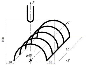
Figure 2 Use of G18 instructions
1) Radius compensation in different planes
The tool radius compensation is compensated by the G17, G18, G19 commands in the selected working plane. That is, when the G18 command is executed, the tool radius compensation only affects the X and Z movements, but has no effect on the Y axis.
The cylindrical surface shown in Fig. 2 is milled, and the tool is a spherical end mill with a radius of 10 mm. There are two programming control points, namely the tool tip and the center of the ball. The center of the ball is used here. O0001
N1 G9054G18G00X60.0Y0S1000M03;
N2 Z0;
N3 G91G01 G41X-20.0D01 F100;
N4 G02X-80.0I40.0;
N5 G40GG0lX20.0;
┇
┇
N22vG90G00Z100.0;
N23vX0 Y0M05;
N24 M30;
Next page
Hight Quality office paper cutter utility knife, with spare blades included, SK5 forging, sharp edge, widened and thickened blades, 3 burst utility knife, more convenient to replace the blade, thickened alloy blade, still sharp after breaking, 11 Sectional cutter head design, suitable for both household and industrial use, suitable for fabric cutting, cardboard cutting, stationery cutting, and plastic tube cutting. It is a must-have good helper for the home. The rubber-coated type absorbs sweat and does not slip, automatically locks, and is safe and efficient.
Knife Tools,Utility Knife,Box Cutter Knife,Stainless Steel Utility Knife
Shang Qiu Runda Measure Tools Co,.Ltd , https://www.rundahandtools.com