Aluminum cylinder head production line process design
September 28 06:04:59, 2025
Pursuing quality and output efficiency has always been the core goal of the company. In the design of production lines, the key is to minimize non-value-added working time, reduce manufacturing costs, and improve productivity while ensuring the quality of machined parts. This not only reflects the essence of lean production but also represents a continuous effort to optimize process design.
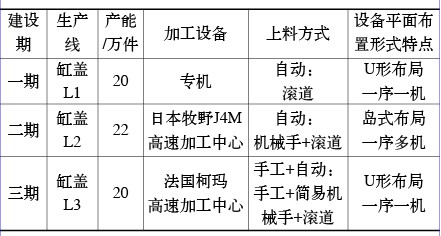
In the industrialization of the first three phases at Shenlong Company, there are three types of production lines for TU series engine cylinder heads (see table below).
Production line overview
Each of these production lines has its own unique features. During the initial phase, due to limited product variety, special machine lines were used. However, as product diversity increased over time, the production mode became more flexible. The second and third phases transitioned from dedicated machines to CNC machining centers. During this transformation, improving output efficiency became a major focus for the factory. Based on practical experience, this paper explores several challenges in the production process, analyzes them from the perspectives of quality assurance, reducing idle time, and enhancing production efficiency, and proposes new ideas for the process design of aluminum cylinder heads.
**Leveraging High-Speed, Flexible Cutting Equipment**
With the rapid growth of automobile production and market competition, the need for quick model changes has become increasingly important. The cylinder head is one of the most complex components of an engine and is gradually being made from aluminum alloy instead of cast iron. Therefore, the production line must be equipped with high flexibility and high efficiency.
Advancements in drive systems, control technologies, materials, tools, testing, and safety have led to the widespread use of high-speed machining centers. These machines offer stable performance and are ideal for mass-producing aluminum cylinder heads. For example, the L2 and L3 production lines at the company have adopted high-speed machining centers.
**Key Advantages of High-Speed Machining**
1. High-speed cutting is well-suited for aluminum cylinder head processing, significantly increasing machining efficiency and shortening cycle times—especially for small oil holes like the 24 φ3mm holes.
2. It reduces workpiece heating during machining, which helps maintain dimensional stability and minimizes tool wear, particularly when milling thin-walled structures like combustion chamber surfaces.
3. High-speed cutting ensures better surface finish and accuracy, meeting high-quality requirements for critical areas such as hydraulic tappet holes and cam bearing holes.
4. It facilitates multi-variety production, making it easier to switch between models and reducing changeover costs. For instance, the L2 line supports mixed production of four varieties, while the L3 line handles two.
5. It allows for easy adjustment of cutting parameters, optimizing both quality and tool life.
6. High-speed machining centers enable efficient "centralized processing," reducing auxiliary times such as tool changes, part loading, and positioning, thus improving overall output. However, speed alone does not guarantee efficiency; it's crucial to evaluate cost-effectiveness and compatibility with materials and tools.
**Optimizing Production Line Layout**
1. **Maximizing the Benefits of Machining Centers**
With the growing use of high-speed CNC machines, process concentration becomes a key advantage. By adopting a “one-order multi-machine†approach, multiple operations can be completed in a single process, helping to maintain production rhythm. The L2 line uses a parallel “sequence and multi-machine†layout, while the L3 line follows a U-shaped, single-machine configuration.
The L2 line offers greater efficiency and lower costs due to:
- Reduced downtime if one machine fails, with minimal impact on overall output.
- Easier problem analysis due to consistent processing across machines.
- Lower tool inventory costs due to shared tools among multiple machines.
- Improved accuracy through reduced positioning errors.
- Smaller footprint and fewer equipment requirements.
- Easier maintenance and automation adjustments.
- Fewer operators needed.
2. **Choosing the Right Feeding Method for “Sequence and Multi-Machine†Layouts**
Different feeding methods are used, including robotic feeding, manual + pneumatic spreaders, and manual + flipping boards. Each has its pros and cons.
Robotic feeding (as seen on the L2 line) allows for high automation, multi-variety production, and reduced labor intensity, but comes with higher investment and maintenance costs. Manual + pneumatic spreaders are more cost-effective but require more human intervention. Manual + flipping boards are simple and low-cost, but may risk damaging parts and involve higher labor demands.
3. **Minimizing Inspection Time Through Smart Layout**
To reduce idle time, inspection tools should be placed close to the loading/unloading area. This reduces transport time, lowers the risk of damage, and makes inspections of complex features like valve seats and hydraulic tappets more convenient.
Figure 2: Gauge placement near the operating position
By optimizing layout and integrating advanced technologies, the company continues to enhance efficiency, reduce waste, and stay competitive in the evolving automotive industry.