Aluminum cylinder head production line process design
September 28 06:17:08, 2025
Pursuing quality and output efficiency has always been the core focus of the company. In the design of production lines, shortening non-value-added working time, reducing manufacturing costs, and improving output efficiency while ensuring part processing quality are key aspects of process design. These efforts reflect the principles of lean manufacturing.
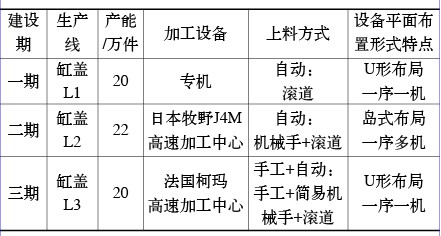
During the industrialization of the first three phases at Shenlong Company, there were three types of production lines for TU series engine cylinder heads (see table below).
Production line overview
Each of these production lines has its own unique features. In the first phase, with a limited product variety, special-purpose machine lines were used. However, as product variety expanded over the years, the production mode became more flexible, and equipment transitioned from dedicated machines to CNC machining centers. During this transformation, the factory placed significant emphasis on improving output efficiency. This paper draws on practical experience to analyze and summarize several challenges in the production process, focusing on quality assurance, reducing idle time, and enhancing overall line efficiency, while exploring new ideas for the process design of aluminum cylinder heads.
**Leveraging High-Speed, Flexible Cutting Equipment**
With the growing demand in the automotive industry, market competition has intensified, and the pace of product changes has accelerated. The cylinder head is one of the most complex components in an engine, and it's increasingly being made from aluminum instead of cast iron. Therefore, production lines must be equipped with high flexibility and high efficiency.
Advancements in drive systems, control technology, materials, tools, testing, and safety have led to the widespread use of high-speed machining centers. These machines offer stable performance and are ideal for mass production of aluminum cylinder heads. For example, the L2 and L3 cylinder head production lines at our company have adopted high-speed machining centers.
**Key Advantages of High-Speed Machining:**
1. High-speed cutting is well-suited for aluminum cylinder head processing, significantly improving machining efficiency and reducing cycle time, especially for small oil holes like the 24 φ3mm holes.
2. It reduces workpiece heating during machining, leading to less deformation, better dimensional stability, and less tool wear—critical for thin-walled parts like cylinder heads.
3. High-speed cutting makes it easier to achieve high surface finish and precision, such as in hydraulic tappet holes and cam bearing holes.
4. It supports multi-variety production, facilitates product changeovers, and lowers the cost of switching between models.
5. It allows for easy adjustment of cutting parameters, improving both processing quality and tool life.
6. High-speed machining centers can reduce auxiliary time for tool changes, loading, unloading, and positioning, thus increasing output efficiency.
However, high speed isn’t always efficient. A comprehensive evaluation is needed. High-speed machines are more expensive, and not all materials or tools are suitable for high-speed cutting. For instance, valve seat rings and conduit materials are often powder metallurgy, which may not be ideal for high-speed operations. Choosing the right speed based on actual conditions helps reduce input costs and improve the output-to-input ratio. Experience shows that spindle speeds between 16,000 to 24,000 RPM are optimal for aluminum cylinder head machining.
**Production Line Layout**
1. **Maximizing the Advantages of Machining Centers**
With the widespread use of high-speed CNC machining centers, the key to effective process design lies in leveraging their capabilities. Process concentration is one of the main advantages of machining centers, allowing for a “one-order multi-machine†approach. Multiple machines can complete various processes within a single stage, ensuring consistent production rhythm.
The L2 and L3 cylinder head lines use high-speed machining centers. The L2 line uses a parallel “sequence-multi-machine†layout, while the L3 line follows a U-shaped “single-single-machine†arrangement.
In terms of efficiency and cost, the L2 line demonstrates clear advantages:
- If one machine fails, others can still operate, minimizing downtime.
- Problem analysis becomes easier when the same process is repeated across multiple machines.
- Tool inventory can be reduced due to shared processing content.
- Process concentration reduces positioning and clamping errors, improving accuracy.
- The total number of machines can be fewer or similar compared to a single-machine setup.
- The production line length is shorter, saving floor space.
- Equipment adjustments are easier for continuous production.
- Fewer operators are required.
2. **Choosing the Right Feeding Method for “Sequence-Multi-Machine†Layouts**
“Sequence-multi-machine†layouts typically use mechanical arm feeding, manual + pneumatic spreader feeding, or manual + assisted flipping. Each method has its pros and cons.
Mechanical arm feeding (as seen in the L2 line) offers high automation, ease of handling heavy parts, and supports mixed-flow production. However, it requires a high initial investment and has higher maintenance demands.
Manual + pneumatic spreader feeding (used in the L3 line) is more cost-effective but requires more manual effort and careful layout planning.
Manual + assisted flipping (shown in Figure 1) is simple and low-cost, but risks scratching parts and is unsuitable for heavier components.
**Optimizing Inspection Tool Placement**
To reduce idle time, inspection tools should be placed as close as possible to the loading/unloading area. Previously, parts were inspected on dedicated tables, which was time-consuming. By placing inspection tools next to the operating position, the transportation time is reduced, labor intensity is lowered, and the risk of damage during transport is minimized. This is particularly beneficial for inspecting angled features on the cylinder head, such as ducts, valve seats, and hydraulic tappet holes.
Figure 2: The gauge is placed on the raceway next to the operating position