Design of a Computer Monitoring System for Hydropower Station Based on PCC
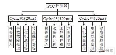
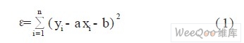
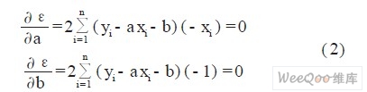
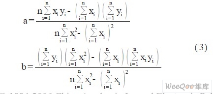
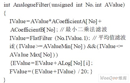
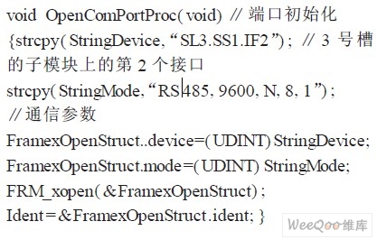
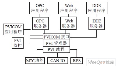
introduction The advantages and disadvantages of the hydropower station computer monitoring system represent the level of automation control of the hydropower station in a certain sense, which directly affects the unit's operational safety, power quality and production efficiency. From the current development needs of the hydropower station automation level, the programmable logic controller PLC (Programmable Logic Controller) in the high-speed data processing, network communication and system expansion and other aspects of the ability can not meet the requirements, and a new generation of programmable computer controller PCC (Programmable Computer Controller) not only has the advantages of stable and reliable PLC, but also has the powerful data processing and communication capabilities of industrial control computer, rich programming language, and many advantages have made it capable of large-scale distributed control and complex control process. The system described in this paper is based on the B&R 2005 series PCC. The control program is programmed in ANSI C language. At the same time, the unit simulation is filtered by the least squares method. The PCC Control System is compared with the external intelligent device and the host computer based on the frame driver and OPC Server. Communication constitutes a more advanced open monitoring system for small and medium-sized hydropower stations. 1 System monitoring mode and composition The computer-based monitoring method CBSC (Computer-Based Supervisory Control) is a computer monitoring method commonly used in hydropower plants at home and abroad. The main feature of the CBSC mode is that the main monitoring functions of the power plant are all realized by computers, which greatly simplifies the conventional control devices, leaving only a part of the local operating equipment for special situations, but because of the local control unit LCU (Local Control) located at the lower level of the monitoring system. Unit) generally uses PLC as its control core, and it is not powerful enough in data processing and communication. Users need to invest a lot of money to expand or upgrade the system, and PCC successfully solves this problem by relying on its rich and flexible communication module. The problem makes the CBSC monitoring method more flexible and effective. Combined with the actual situation of the Yilang Lalang Hydropower Station in Guangxi, the system is based on the B&R 2005 series of medium-sized PCCs and designed the monitoring system in CBSC mode. The system control core PCC consists of a series of independently packaged box modules, the basic module includes a power module and a CPU module, and the expansion module includes an I/O module, a communication module, and the like. In this system, intelligent devices such as governors, fuel gauges, and temperature patrols can stably communicate with PCC and send data to PCC, while PCC monitors terminals with host computers via Ethernet (based on TCP/IP protocol). Communication also sends data to the display unit on the LCU. This mode makes up for the shortcomings caused by the dispersion of equipment, so that the operating personnel can monitor the running status of the unit on the upper computer or man-machine interface to realize a real distributed monitoring system. The structure of the system is shown in Figure 1. Figure 1 System structure 2 Local control unit programming 2.1 Control program design 2.1.1 Task layer design The PCC's operating system is a time-sharing multitasking operating system that optimizes the control system for better stability and real-time performance. In the control program, each task program module is located under the task layer with different priorities according to its own importance and real-time requirements, and performs different functions. For example, accident handling directly affects the safe operation of the turbine. Therefore, the module is placed in the task layer Cyclic #1; and modules with relatively low real-time requirements, such as communication program modules, are placed in the task layer Cyclic # 4 in. Figure 2 shows the task layer distribution of each task program module of the control program (the time in parentheses indicates the cycle time of different task layers) 2.1.2 Analog Processing Design The unit simulation such as pressure and temperature plays a vital role in the normal operation of the entire turbine. Therefore, the analog quantity needs to be filtered to ensure the accuracy of the data. The PLC-based control system generally filters the analog values ​​by averaging the values ​​obtained by the analog-to-digital converter N times, which has the disadvantages of poor reliability. The program fits the analog data based on the least squares method, and adjusts the parameters according to the changes in the characteristics of the sensor, thereby improving the reliability of the data. The least squares method is to select the appropriate a, b to minimize ε in equation (1). Since ε is a function of a, b, it can be known that the method of extremum is satisfied: Solve a, b: then: Where Yi is the data processing result of the i-th analog channel; Xi is the initial value of the i-th analog channel read from the sensor; ai, bi is the parameter corresponding to the channel; n is the average number, the program is generally Take 20 times. The analog processing module part of the program is as follows: 2.2 Communication program design The communication between the LCU and an external device such as a fuel gauge is based on a frame driver. A frame driver is a software toolkit between an application and a hardware interface that causes frames to be sent and received as a stream of bytes without the need for a driver to operate on those frames. a. Initialize. At the beginning of the communication, the port is initialized by the frame command FRM_xopen(enbale, device, mode), whose parameters define the interface device, interface parameters, and data transfer status. b. Data transmission and reception. The function FRM_xopen( ) returns the address of the buffer and its length after initialization, and then calls memcpy( ) to write the data to the buffer and send the data out. The process of data reception is basically the opposite of the transmission. The frame driver first calls FRM_read( ) to read 1 frame of data and puts it in a buffer, and then reads the contents of the buffer by memcpy( ). The communication module part of the program is as follows: 3 PC monitoring implementation 3.1 OPC server The upper computer monitoring function is to realize the sharing of the unit data information by the upper computer configuration software for the bridge by means of the OPC (OLE for ProcessControl) server. OPC is an industry standard that defines common interfaces for hardware devices, software, and systems from different vendors, enabling interconnection, communication, and operation between different systems, devices, and software in process control and factory automation. The advantage of the monitoring system using the OPC protocol to communicate with other field devices is that no matter whether the hardware device uses a standard communication protocol, the manufacturer only needs to provide one set of OPC servers, which can support most of the monitoring software, and does not need to The communication protocol details are provided to the software vendor. The OPC server software is mainly divided into an OPC server object module, a server interface module and an OPC driver module. The three modules share data through the same main memory data area, and the shared data can be solved by the use of threads synchronization and mutual exclusion technologies. Protection issues. In this system, after the upper monitoring computer is started, the system automatically loads a system module called “PVI†by B&R, and the PVI starts communication with the OPC server encapsulated in the PCC operating system (based on TCP/ in this system) IP protocol). The core part of the PVI is the “PVI managerâ€. In the “PVI managerâ€, the user can selectively define the data transmitted from the OPC server as needed. The basic structure of B&RPVI (see B & R 2005 User's Manual, 2004) is shown in Figure 3. Figure 3 PVI basic composition 3.2 Configuration program design The configuration program of the system adopts the design of Beijing Yakong “Kingview 6.03â€. "Kingview 6.03" has a comprehensive alarm and event system, a reporting system and an Active X control that supports the Windows standard. It also fully supports the OPC standard. It can easily realize data sharing with the PCC OPC Server through PVI, such as switching. Monitoring functions such as volume monitoring records and event sequence recording, accident recall and fault recording, automatic power generation control (AGC), and automatic voltage control (AVC). 4 Conclusion This paper introduces a new and efficient hydropower station computer monitoring system based on the rapid development of PCC technology. Based on the B&R2005 series PCC, the system realizes various control and protection functions of the unit based on the least squares method to filter the unit simulation. Based on the frame driver and OPC Server, the PCC control system and external intelligent equipment are implemented. The communication of the upper computer constitutes a more advanced open monitoring system for small and medium-sized hydropower stations. Since the on-site installation and commissioning, the monitoring system has been operating safely and reliably for nearly one year. PCC will gradually replace PLC with its powerful performance, and it will become an indispensable part of hydropower plant automation transformation.
Dot Light or Pixel Light, be used for building decoration, indoor and outdoor lighting, low power, small size, flexible insstallation.
1. Flexible strands of attractive mid-size, low profile high brightness RGB, RGBW or Whites LED pixel node lights suitable for applications on building facade mullion intersections for a distinctive lighting decoration or mounted into node array formation to create huge full color graphic display; Dot Light,Led Dot Light,Landscape Lighting Dot Light,Low Power LED Dot Light,Addressable LED Dot Light,Outdoor Lighting Dot Light StrongLED Lighting Systems (Suzhou) Co., Ltd. , https://www.strongledcn.com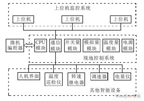

:
2. Cree, Osram or Lumileds LED brand choice provide good color mixed and a wide view angle;
3. Built-in PWM high brightness contrast level control for smooth and consistent color change effect;
4. Polycarbonate housing with clear flat UV-resist diffuser, weather-sealed with silicon polymer for maximum lifespan;
5. Use standard CAT5 for signal transmission. Customizable pixel node pitch and lead cable length;
6. Easy mounting and installation with stainless steel spring bracket. Single node mounts can be positioned individually to support complex structure geometries;
7. DC24V input. DMX control. Ingress protection at IP66.